

Immutable Marbles Build Guide
- filip
- Sep 5, 2025
- 3 min read
Updated: Dec 23, 2025
18HP Random Sampler Module
Difficulty Level: Beginner/Intermediate
Time: 1-2 Hours

What you'll need
Immutable Marbles DIY kit
Soldering Iron
Solder
Side cutters
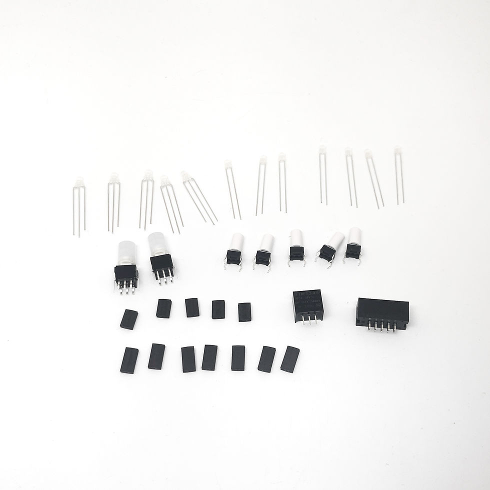
Verify parts
Begin by pulling out all of the parts included in your Marbles DIY kit and reference the bill of materials to ensure you're not missing anything.

Placing and soldering components
Begin by placing the 10-pin header on the backside of the PCB in the orientation shown below. Make sure the tooth in the box header is facing the right way (match it up with the footprint!)
Start by soldering a single pin of each component and then checking alignment and orientation. If necessary apply heat to the joint you just soldered and adjust until the components are straight and flush.
Finish soldering the rest of the pins.


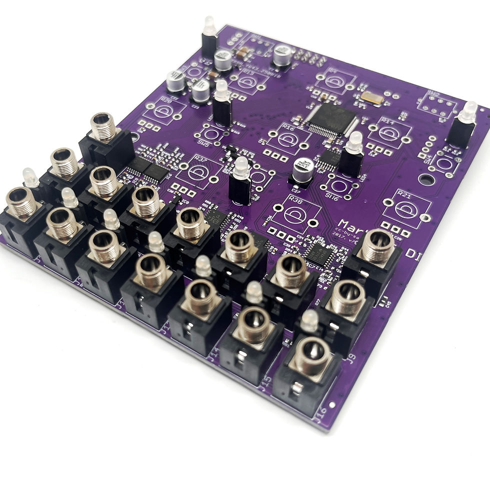
Most other components, except for the DC-DC converter will be placed on the front of the board.
Place all 16 jacks and solder them from the backside. Each jack has three pins to solder


There are two types of LEDs in the Marbles kits - 3 pin LEDs and 2 pin LEDs. Each type has it's own specific length of standoff. The 2-pin LEDs get a 10mm (longer) standoff, while the 3-pin LEDs get a 0.3" standoff. Insert the standoffs to get the LEDs ready for soldering.


We will start by soldering the 5 3-pin LEDs. These have a flat spot that matches up with the footprint on the PCB. The flat sides face upwards. Clip the excess leg with side cutters.


The 2-pin LEDs are installed at the bottom of the board, one for each output. There is no indicator for polarity for these, the LONG LEG needs to be soldered on the LEFT SIDE.
For these LEDs, using the front panel as a positioning guide is a great help.


At this point, all your jacks and LEDs should be soldered.
Let's solder the buttons next. The 5 white cap buttons can go in 2 out of 4 directions (diagnol symmetry)

The big buttons do have a direction - They have a built-in LED so they need to be soldered with the green dot matching up with the dot printed on the circuit board.

SW1 needs to have its legs trimmed so the DC-DC converter can flush mount on the bottom. If you mount the DC to DC converter on the top, the panel will not sit flush!


(FIRST BATCH ONLY) The DC-DC converter does need to be installed the right way around, pay attention to the photos to see how it should be mounted.
EDIT DECEMBER 2025 - The new boards were adjusted to have the footprint on the bottom instead of the top. If your footprint for the DC DC converter is on the bottom of the board, please follow the footprint instead of the photos here.
It's time for the last components - the potentiometers. They are all the same value - B10K.


Install your panel, washers, nuts, and knobs and you're all done! The two big knobs are for RATE and SPREAD.

Calibration
Marbles comes pre-calibrated so you do not need to do any additional calibration. The kits come with a sticker containing the calibration offsets and coefficients for each output - this might be handy to hold on to if you ever need to compile your own code.


Comments